


FITTING GEARBOXES AND MB5 GEARBOX
As with other parts of the Lambretta engine the gearbox area is very misunderstood. If you look at it as a whole – yes it looks complicated – nearly 50 parts – break it down into smaller sections and it becomes a simple job.
All that’s needed is a bit of ‘common sense’ and building a gearbox becomes a simple thing to do.
This is a long winded article and I may repeat myself in places but it needs to be – to get to all the points and problems across!
MB 5 gearbox update is at the bottom of the article.
GEARBOX INTRODUCTION
The gearbox fits between the rear hub bearing and the end plate and there are a number of moving, precision machined parts inside this gap. Machining all these parts to fit and work is difficult to make in a mass produced engine and get everything perfect in every way so each part fits and works. I’m told by F1 engine builders it’s the same, they order parts from suppliers with drawings and all sorts come back and don’t fit and are scrap and they have to start again. So what hope do we have?
In the perfect world you would think it’s not hard to make parts which are exactly the same plus or minus a few thousands of an inch! Any of you who have tried to assemble a casing with miss matched parts old or new from Italy, Spain or India will know what a pain they can be. Throw into the mix that some parts are made by pattern manufacturers then you can be in real trouble. Take a hand full of the same parts and closely inspect them and you will find differences. Sometimes Spanish engines and parts only fit together perfect – add some Italian parts and you could be in bother and the same the other way round!
With this in mind right from the beginning there will be variations in machine tolerances, this is why they make gearboxes with varying sized shims and it also allows for parts to wear and be readjusted later on.
When I’ve had a real untouched Innocenti engine for a strip down they really are a wonder! Everything is right. For a shopping trolley manufacturer they basically got everything right and it all fits, turns over and works.
Now take an Indian engine, they are not bad – well – defiantly not perfect – but not bad – but could be better! But take a new Indian casing and buy everything new as a ‘bits of pieces’ and a gear box can be a nightmare! As a Scooter mechanic I wonder what fun they must have in the factory putting engines together. If you strip an Indian engine you realise they have been thrown together without the care Innocenti had. I’ve even stripped a new SIL engine and the end plate nuts were loose it wouldn’t have got 50 miles!
If all the casings and machining tolerances for parts are done correctly you would expect everything goes together perfect…….. but they don’t!
Ok – so much can effect how a gear box goes together, some go together easy and perfect, others need a tweak with a shim and others are a nightmare, coming apart for days on end with special machining and special shims.
So what affects a good rebuilt gearbox to a pig of a box?
You need to understand the common sense basics to know what is wrong and where. And right from the start of fitting the rear hub bearing it starts…………. never expect everything is correct, expect it to be wrong and it should be easier.
Break it down to these areas.
DESCRIPTIONS OF THE PARTS INVOLVED IN THE GEARBOX AREA
-
Engine casing
-
Rear hub bearing
-
Layshaft
-
End Plate
-
Gear Cluster
-
Gear Selector
-
Gear Selector spring
-
Wishbone and Pawls
-
Gear selector arm
-
Gears
-
Gear Cluster
ENGINE CASING
All engine casings can vary where the machining is. A rear hub bearing can be further in towards the gearbox or further away! This will set the standard to where the layshaft will be and where top gear will be when selected and will set what main gear shim will be required.
The machined area where the end plate bolts down can also be variable, as can end plate heights. These all affect the gap between the end plate and rear hub bearing and ultimately how the gearbox sets up.
REAR HUB BEARING
A rear hub bearing can vary in it’s thickness. It can sit up or down in the casing again affecting where the layshaft will be, the same as a casing machined height. Today modern remade bearings do vary and it’s the same for our own older MB bearings. But non of this matters if you understand parts vary. It may be a case of – you need an over sized gear shim at 3.00mm or a special under sized shim at 1.60mm, or it could be within normal Innocenti gear shimming tolerances of 1.8 – 2.8mm or you could need a special MB shim to sit between the layshaft and bearing to take out more play or it may need a layshaft machining!
You could have a casing machined ‘out’ away from the end plate, you could have a rear hub bearing again ‘out’ it may only be a 0.10mm here or there but the extreme could easily be near 1.00mm needing a large shim or the extra spacer shim. You could have an ‘out’ casing and a ‘in’ bearing putting the standard size to near perfect. You could have an ‘in’ casing and an ‘in’ bearing needing a small main shim or even need the layshaft machining.
LAYSHAFT
Throw into the mix a Layshaft. The length varies, not in one section but in a few areas. Layshafts need looking in these different areas, especially if your having a problem;
-
The height of the area of the shaft where the 4 loose gears rotates, this will effect if the gearbox can be shimmed or not
-
The length below it, which effects adjustment height and where 1st gear will be in relation to the end plate and what gear shim is required
-
The length of the area where the needle roller bearing runs can vary, effecting if a needle bearing shim is required or not
-
Diameters of the layshaft where the gears run can vary, making them sloppy or perfect, especially if a used layshaft is used
-
Also where the layshaft needle bearing runs, these can wear, break up, be perfect or tight
-
It has been known the area where the selector balls run is drilled incorrect and can vary, effecting gear selection or makes a noisy clicking gearbox in neutral.
END PLATE
Of course these vary from new and different manufacturers, affecting gear shimming or where the gearbox bearings are in line to the rear hub bearing and the cluster needle bearing bush. An end plate is machined in the factory to the casing to keep the bearing holes inline and are held by the stud and dowel holes. New SIL engine casing and endplates, are numbered by paint to match an engine casing. Italian ones are stamped with a number on the end plate.
Take a miss-matched end plate on a casing and you can find the stud holes don’t line up or fit and the dowel holes are out. If you try, the layshaft and the cluster can be pulled to one side which wears out bearings. Some may fit the studs but the dowels will be out of line. Machining heights of the casing where the end plate goes can vary as could the height where the end plate ball bearing fits.
If the end plate is machined out of line and stud holes are off set you can drill the end plate holes from 7.5mm to 8.5mm or you can elongate them to allow stud/screws to fit. You can fit the gear box end plate without dowels, when it’s all correct and tight you can knock the dowels in last and center punch the end plate to stop them falling out, this is my method with any engine.
Some endplates may need a 7mm drill running down into the casing first to true up the dowels. If the casing is damaged and over sized then you may need to drill through with a 7.5 or 8mm drill to fit oversized dowels, MB sell these. When you’re finally doing this, use a little loctite on the dowels in the casing. The end plate needs to be a simple free easy fit on the studs and dowels. If it’s a free fit the layshaft and cluster aligns the end plate for you or as best it can. Also the end plate ball bearing needs to be an easy fit over the cluster. If it’s tight, you’re forever hammering the end plate on and off. This is normal in most engines if tolerances are not correct on the cluster and inner ball bearing faces. These sizes do vary……….. ideally an easy fit is best – if you can fit and pull off by hand or with a little leverage this is best.
GEAR CLUSTER
Cluster heights vary between the length where the shim fits to where it sits under the cluster ball bearing. Most clear and spin free, some after market clusters lock up solid as they are machined wrong. Removing the shim usually cures this problem. Most casings vary on where the cluster needle bearing bush fits in the casing. Most Italian/Spanish casings have the bush fit near flush to the casing and some – mostly Indians fit very proud, again this will effect where the cluster fits between the end plate. So some spin and some lock up, again removing the shim is a simple cure. Ok it’s not correct, but if you’re using some common sense, what does this shim actually do? Well it should slow the needle bearing down but engines run with no shim and give no problems, the needle bearing can float free. It can’t go any where, it just sits there and spins!
GEAR CLUSTER OUTER BUSH
This is a tight press fit in the casing, they hardly ever wear out unless a gearbox has been run dry of oil. If this has happened you can see the hardened surface broken up or shows wear marks. Most are perfectly fine to reuse, just make sure they are clean with no crap behind the gap and that they are tapped home fully. If you fit the cluster and needle bearing into the casing it should spin free and have very little rock.
If the bush needs to be removed it is quite hard to do, there is a genuine tool which does work but are rare. But these bushes can be very tight! Heat always works to free these. Another good idea is a perfect machined solid bar that fits into the bush. Put some grease under it then hammer the bar down, this forces the bush out. Refitting a new bush is easy, clean out the casing, there is a outer gear cluster bush shim that fits between the casing and the bush, these shims don’t wear if it’s good, reuse it and they only come in one size. Heat helps when fitting the bush but you get no idea how tight the bush is, so I do with bush and casing at room temperature. If it hammers in tight using a drift then great, if it’s loose going in you can loctite it into position. If it’s really loose you can center pop the casing around the holes this will tighten it up. This bush needs to be tight or it will spin like a bearing when the engine is running and wear out the casing.
GEAR SELECTOR (CRUCIFORM)
In general Innocenti, Spanish and SIL gear selectors are very good. But 40 years of making them by different companies and you can get a difference in where the selector balls run which effect where the dogs of the selector are when locating gear. This can mainly happen with after market Italian and Indian gear selectors. If this is wrong you will notice in neutral there will be some clicking as the 1st and 2nd gears spin. Out of line gear selectors can either touch 1st gear or 2nd gear. It’s an easy check with an engine face down and the crankcase side facing you as gravity drops the gears into position. It is much more difficult to do this with the engine on the stand as the gears want to rock forward making this test harder. You can lightly grind the selector dogs to clear, so the clicking stops. And it has been known to machine an inside face of a gear for them to clear. As the gears move around on the layshaft to check this clicking, the gear box needs assembling correctly with a correct shim to hold the gears as tight as they can but still spin. Old gear selectors can be used, check the dogs are not to worn and if in doubt use a MB strong spring – it’s surprising what bad gear selectors can be used with our spring without jumping out of place. Check where the pawls run and at this point if you can fit the wishbone and pawls to make sure it runs free, do some filing or polishing if there’s a high spot.
GEAR SELECTOR SPRING
This makes no difference to setting up the gearbox, but it’s very important to make a gearbox work correctly. If you use an old original spring the chances are it will have lost it’s strength and offers no power to hold the gear selector balls and selector in position and the selector can jump under load and you either get a missed gear or a bucking bronco. This will especially show up if the selector ends are worn or the internal gears are chipped and worn. Running with a weak spring that lets the gears jump will damage the selector and gears in no time at all. Ok gear selection is much easier using a weak spring on the clutch hand but it’s worth changing to our stronger MB spring. The stronger spring holds even the worst worn out gear in position and every engine should have one fitted. The only down side is, some have complained it’s hard to select gear! This is totally cured with modern day friction free cables. I could, if I wanted on my bike rebuilds, select from 1st to 5th in one go with hardly any pressure on the handlebar mechanism. So it’s very important to set up the gear box internals and the externals right back to the handlebar rods/levers/rollers.
WISHBONE PAWLS
This simple mechanism is very important, not really to do with fitment of the gearbox but how it selects a gear and is mainly over looked. The pawls are weak and not a great design and can wear. Even new wishbones can be machined wrong and have sloppy pawls. Some wishbones are thicker in the pawl area and can lock on the casing trying to make top gear jump as it stops the pawls sitting fully home and only half selects top gear. Some wishbones can be closed up causing the layshaft and selector to be tight without even fitting a gearbox, these can easily be prized apart with a screwdriver on assembly to loosen the movement. If on assembly, the wishbone touches the casing in top gear (4/5th) selection then the wishbone can be ground to clear the casing, sometimes on older engines you can see two marks where the wishbone has worn into the casing. Before the gear selector is fitted onto the layshaft and in the casings fit your wishbone and pawls and run them in the groove on the selector – they should run free but some can be tight in places, it’s easy to do some small mods to make them run free.
MB have addressed this issue of sloppy pawls and now offer pawls with an oversized shaft. All you need to do is drill out the wishbone to 5.5mm, chamfer both sides and make sure the pawls spin free. Early MB pawls were threaded and the nut can be tighten up then back off a bit so the pawl ran free. We always said loctite the nuts but not too much to lock the pawl. Later pawls we cut out a potential failure point and stopped using nyloc nuts to avoid them coming loose. Our latest spec oversized pawls fit from the inside out the same as a J range used. Just grease them to hold them in place, once fitted they can not come out. This Mb conversion will give a more solid gear selection all the way to the headset.
GEAR SELECTOR ARM
The gear arm is probably the highest wear item in the gearbox. The shaft hardly ever wears (unless the engine has been sand blasted and not cleaned correctly) but the arm on top of the gearbox does. The gear arm needs to be perfect – as does all the gear linkages, cables and headset controls. If one part of the linkage is wrong it will tell in how the gearbox works.
There are two types of gear selector arms
- Li, Tv, Sx types, these are the ones with a loose arm that slides down the splines and bolts onto the gear selector shaft
- Gp type, this is the one where the arm and the splines are in one part
The Li, Tv, Sx type is not to be preferred. These tend to come loose on the splines or the bolt holding it together comes loose or snaps. When this happens it’s worth trying a new high tensile bolt to see if it tightens up. It’s easy to get to if you remove the rear hub and wheel. If your using all new or perfect parts when your ready loctite the splines and bolt to make it solid and then works fine.
The Gp version is to be preferred as it eliminates the bolts and splines coming loose. The down side is – if you need to remove it you have to strip the gearbox totally!
The main part that wears on both types is the little peg that the tie rod pivots on. Our method for a longer lasting arm is to grind off the little peg, drill it out and fit a stud with a straight shank which uses a 6mm nyloc nut when fitting the tie rod. This gets rid of that silly little circlip as well which causes so much trouble. Leave the nut slightly loose, grease it and it will last much longer. If the stud should wear you can replace the stud or the bush or Tie rod. Today MB remake the GP gear arms with studs already fitted. Always check the selector arm is a good fit in the engine casing bush, if not these are easy to replace. Always check there is no wear in the engine casings at the bottom – this can wear and is a major repair as there isn’t a bush only an alloy engine casing.
GEARS
As with everything else, gears change in dimensions. Not just with all the unlimited gear boxes, gear ratios, gear diameters (see our gearbox section in the Tech-Site) but in the widths when they stack together! In that perfect factory engine everything fits and works. But over the years from different manufacturers, sizes altered. You would think a Li 150 gearbox would be the same from all 3 models (Series 1, 2, 3). On paper the gear ratios are the same, the number of teeth are the same but it’s been know that the width of machining can vary. If you fit the 4 gears to a layshaft correctly the 1st gear should always be slightly higher than the layshaft. By miss matching parts 1st gear can be under the layshaft. It could be you have the wrong layshaft or an oddball gear, you have been warned – check this out before the layshaft is fitted into the rear hub bearing.
Always check the condition of the loose gears. Check each tooth is there and not chipped off, check there are no cracks on a tooth and check the inside dogs where the gear selector fits. Check the gear teeth are not worn, you can see this if you imagine the cluster gears rubbing on the gear teeth, it’s quite common to find worn teeth. The inner castellated dogs on an old gearbox chip away or are worn on a taper. With the MB spring you can get away with murder. But if the internal gear dogs are totally rounded off swap the gear or gears. Check for pitting and rusting and check the gear runs free on the layshaft. Some can be tight and some can be loose. Some can be tight as you spin the gear on the layshaft check it out and free them off with emery paper or a grinding stone. And always check the condition of the 1st gear kickstart teeth, these are always chipped on old gearboxes. Pick the best if you have a handful. It’s ok if the odd tooth is chipped, if there are many chipped or missing replace it. And always check the teeth on the kickstart plunger, changing for a new one can help prevent more damage. If you know your kickstart lever slips constantly or every now and then, check the teeth and the gearbox shim. Standard cut gear plunger teeth are machined wrong and don’t drop into the 1st gear teeth correctly. MB looked into it and designed the teeth so they drop correctly into both teeth and select on the 1st gear teeth to stop slipping.
GEAR CLUSTER – INPUT SHAFT
Again these vary in heights. The height of the cluster that fits underneath the end plate roller bearing and between the engine casing. Most Lambretta gearboxes fit perfect with lots of movement and don’t cause problems. What usually varies is the height of the cluster outer bearing sleeve that fits into the casing. Some can be flush or near flush others – sit higher. If it’s high always check it’s fitted correctly as these can move out in use. You can also find some aftermarket clusters are longer and it maybe a case of removing the shim normally used between the cluster and cluster bearing. Always shift your eyes over each gear tooth to see if any are missing. The most common problem with a gear cluster is where the needle roller runs, these can wear out and break up. Gp125/200 are the worst so always check this area out. If yours is worn and you have no spares, MB offer a repairing service by fitting a new bearing bush onto the cluster. The cluster needs to fit into the end plate ball bearing quite easily. Some do with no mods and some don’t. At this point its worth doing the mods. To check how tight it is, tap the cluster into the bearing with a soft hammer, if it’s tight then the area that fits into the bearing needs a little tweak. Depending on what you have at hand depends on how you can do this. Easy – is mount it in a lathe or vertical drill and lightly polish the area with some emery cloth. Hard – is you can use a flat file with emery cloth wrapped around it and you can steadily grind it away. Clusters are hard so you can’t file them!
MOVING ON………………………….
Using the ‘simple basics’ the gearbox assembly should become a little bit easier to understand.
So where do you start? As I’ve said, presume nothing fits and expect a gearbox to be a right bastard of a job, if it goes together correctly then it’s a bonus! Presuming we are building a new gearbox, everything should be clean and tidy as we are assembling the gearbox area. MB offer a Ultra Sonic cleaning service for oily gearboxes. Even if your overhauling or repairing a gearbox with oil around it’s no problem if you clean the areas mentioned. Do your self a favour and buy a tin of brake cleaner, it’s a wonder at cleaning oil off! A quick squirt and dust and crap are all washed away and evaporates to start again, ideal to clean a bearing out if your reusing one.
Original untouched standard gearboxes from an old Innocenti engine are rare these days, if it’s an old UK model the chances are it’s been broken, stripped a few times or played with. Take an untouched style of rebuild or one that has been professionally rebuilt before and it should go back together ok on an overhaul…….. that’s IF you use the original rear hub bearing, layshaft, gear selector and gearbox box. You can change the needle bearings and providing you put everything together correctly and the gears are fitted the correct way round it will go back together and all you have to check is the gearbox large shim.
If it locks up, then all it will be is the layshaft hasn’t been pulled in correctly so the gearbox will be tighter than when it was taken apart. Or the usual over looked trick is, you have to pull the cluster into place by fitting a clutch spider and tighten the nut. This is because as you tap down the end plate with a tight end plate ball bearing the cluster is pushed tight onto the needle bearing area. If it’s tight on a known good gearbox it will be human error on the rebuild, not miss matched parts. So it’s important simple basics are done from the word GO!
IF you have to change any of the following
-
rear hub bearing
-
layshaft
-
gear or gearbox
-
endplate
-
gear cluster
You will need to follow the procedure I’m trying to tell you. IF you are fitting a total miss match new rebuild or 5 speed it’s all the same, follow the basics and you should be able to assemble the gear box and it should spin, select gear and work for a long time.
Lets not think of this standard original untouched Innocenti barn find type of engine with no miles on it, these should just strip down and fit together easy and create no oddball problems. This strip and rebuild type of work is covered in all the manuals.
A well made assembled gear box won’t jump out of gear and the kickstart will work without slipping and it won’t lock up!
Follow the steps and hopefully it all works out in the end…………
PROCEDURE AND CHECKS FOR REBUILDING A GEAR BOX
-
Engine casing
-
Rear hub bearing
-
Fitting a rear hub bearing
-
Layshaft
-
Checking the Layshaft
-
Checking the Gear Selector
-
Gear Selector Spring
-
Gear Selector Balls
-
Fitting the gear selector spring and balls
-
Fitting the selector to the layshaft
-
Fitting the O ring to the Layshaft
-
Fitting the layshaft into the rear hub bearing
-
Setting up the gear selector shaft and wishbone
-
Fitting the gears and cluster
-
MB 5 Speed
ENGINE CASING
Before you go and fit anything it’s a well known fact the Lambretta gearbox area is a pain, especially the way it mounts in the casing by it’s 6 x 7mm studs and the 2 locating dowels. Now if these are all perfect then it’s fine – it works, even in the highest powered engines. But they do go wrong which is where the problems start. The original nuts are thinner than a standard nut, so don’t hold as tight. The spring washers can splay out on assembly then the nut can come loose. The studs are too short for the job and can come loose. If the studs or nuts come loose the pressure on the gearbox end plate is massive, the end plate will rock and wear and ovalise the stud holes. You should feel this in your riding as the rear wheel will wobble but you don’t always feel it, when you do, its too late the 6 threads could be gone.
IF there is any damage it needs doing before you attempt to fit a gearbox and expect it to last in a full engine rebuild. I’m so used to doing an engine from scratch with a bare casing. Others don’t, it’s a case of ‘I’ve a perfectly good running motor but the gearbox area has gone’! Personally I say totally strip the motor to a bare casing and start again. Ok this isn’t ideal, it may well be one or two threads that need repairing or all 6, this can be done to a full motor in a bike. Anything more than fitting thread inserts and it’s definitely a full engine strip as there will be grinding dust everywhere.
Now ideally in this application the stud and nut design is correct……… BUT as these are known to come loose even in a perfect casing then I look at it like this; A set screw can be used, why? Well if you use a set screw slightly longer than a standard stud you get more surface area of threads, if the top part of the threads are a bit dodgy you can find some better threads further down. If you clean out the threads with a 7mm number 3 plug tap you can get these extra couple of threads and you can use a high tensile 7mm screw (don’t use mild steel screws). When fitting an end plate make sure the threads are clean and dry, you can use a very small blob of loctite which helps to stop the screw coming loose. With this method, the correct way is to use a flat and spring washer which we supply in our MB gear box fastener kits. Personally I only fit a flat washer and with the loctite you don’t need a spring washer and you gain an extra thread where the spring washer is removed. Plus it doesn’t matter how good the spring washer is, if your going to tighten correctly the split spring washer can splay out loosing compression. Our MB spring washers are high tensile so should work well, there are others including stainless ones that are not so good.
If you want to use the tried and trusted stud method we have addressed this area as well by making high tensile studs but with longer threads to fit into the casing and find good clean threads. We’ve also addressed the thin half nut by making them also in high tensile, also matched with our high tensile spring washers. These are available individually as a stud, nut and washer or as a complete set of 6. We also offer extra long studs to help even more with damaged casings.
So what can be done if the threaded area is knackered? Well this depends on how bad it is. If it’s a case of the threads have gone and pulled out and the casting area is still strong then you have 4 choices
1) Repair the 7mm threads with a Wurth 7mm Timesert, Repair a thread with a 7mm Helicoil insert, Repair the thread with a MB special steel or alloy insert
2) Repair the thread by tapping out to 8mm and using a short headed allen set screw
3) Repair the thread by tapping out to 8mm and use a special MB stepped stud or an extra long stud or an extra extra long stud
4) Repair the thread by tapping out to 10mm and use a special MB repair stepped stud
What’s best? Well all types work, best to read our insert and repairing thread article. The Timesert is good but it needs to be a long version and it needs to be fitted correctly as some so called experts don’t know how to fit them correctly! A Helicoil is a spring coil thread, it’s not thought of as been as good as a Timesert but it springs into place and is harder than a Timesert so it’s good IF you do it correctly. Again it needs to be a longer version and fitted correctly as with a Timesert, they need super strength loctiting in place and use a weaker loctite on the stud/screw. If you tap out the threads to 8mm you can use a normal 8mm allen set screw but make sure they don’t hit on the chain when it’s fitted or you can use a domed allen cap head screw which has a shorter head but you don’t get the same high torque from a nut or screw head so you don’t get them as tight. What’s best using an insert or a stepped stud? I would say the stepped stud, not because we sell them but it only has one thread in the casing and the studs are longer getting more grip. Where as an inset has two threaded sides – twice an area to go wrong.
If the thread will not repair because it’s bigger than the over sized thread repair tap, then your knackered. If it’s just the odd one you could leave it and 5 can still hold tight. Or you can weld it up and drill and tap it out. If it’s more – it’s harder. It’s a very difficult job to line up and machine flat by hand or machine. If you try and it’s at an angle which you can’t see, the little needle bearings tend to wear out quickly. It has been known for us to totally weld and repair all 6 holes and the dowels – it’s hard and will never be 100% from new but it could save that rare Tv/Sx/Gp casing and keep it matching the frame, these jobs cost what they cost based on time and can be in the hundreds to repair!
If your not 100% confident in having the skill to repair the end plate area then please – don’t do it! If you’re not confident that your engineer is up to the job don’t give it to them. We get more casings in to repair repairs than simple repairs and these take longer, are harder to do and cost much more. Always give the repair to someone who has done a few of these repairs or you will be in big trouble. You have been warned!
If your working on a race gearbox where the gearbox maybe stripped and rebuilt much more than a road bike then the stud and nut arrangement way could be best to use. I’ve looked at this problem a few times for racing and it’s quiet easy to drill and tap deeper and fit a longer stud, but always be careful not to break through or if you do loctite or silicone seal the stud in place to seal it from leaking.
Let’s look at the dowels, these are drilled in the factory so the endplate is all machined true to the rear hub bearing and cluster needle bearing. Every thing has to be inline for it all to work, but the area is very weak and does tend to split the casing. Again this area is difficult to weld and repair, if the straight holes are elongated which is common you can do a few things
-
Ignore them and don’t bother using the dowels, I’ve run motors like this many times including my own
-
Either drill out to 8mm and have a special stepped dowel which MB make
-
Drill through the end plate at 8mm then fit a 8mm dowel which MB make, any larger and theres no casing left
-
Drill and tap and fit a bolt, but the casing is weak to do this correctly
-
Have them welded up and remachined to your end plate
The rear hub bearing area with the 4 studs is a weak area. There’s not very much alloy around the studs, it’s so thin it’s difficult to drill and tap out to suit a thread repair, 6mm timeserts are best in this application as they are the thinnest. It’s also very thin and difficult to weld and machine back to standard. I’ve scrapped engine casings where all 4 threads have gone and someone has tried to fit a thread insert off set. But given time with special tooling that Mb have made – these can be welded back to standard. Not an easy job but can be done and cost what it costs.
Always check the area where the studs fit for cracking. Casings can crack going away from each stud hole and on bad casings keep going and going. Normally you would scrap the casing but it’s a job MB have started to take on as so many want to restore that Tv, Sx, Gp genuine casing.
The only other area to check on the casing to make a good gearbox is the gear selector bush. These are easy to tap out with our MB Brake pedal/selector bush tool and fit a new one if worn, always check the bush for side to side rock with your selector arm shaft. If in doubt change it or oil can leak as well as give the gear selection a headache.
REAR HUB BEARING
There are various rear hub bearings around made in different countries from genuine Innocenti, Spain and SIL. Apart from SIL it’s near impossible to get these NOS bearings and there are various new remade aftermarket bearings available from various suppliers. Of course a good old Innocenti Li125/150 or similar item is usually fit for service as it’s been bathed in oil for years, if you can get one that’s not rusty. We now ultra sonic clean any bearings to really clean them out if you’re going to reuse an old bearing.
Is a bearing just a bearing? Does it need to be a high load, high revving race bearing? The answer is no! The rear hub bearing is the lowest revving bearing in the engine. Take a final drive ratio from a common Sx 200 at 4.80:1 this means the engine turns 4.8 times to one turn of the rear wheel. Take the Gp200 at 5.20:1 it turns 5.2 times to one turn of the rear hub bearing, the bearing turns roughly 5 times less than the crankshaft! So baring in mind, in a high tuned engine we can still get away with ”to a point” standard flywheel and drive bearings. We certainly can get away with a non high performance rear hub bearing. Add to this, the rear hub bearing is constantly in an oil bath, it’s rare a gear box runs out of oil to melt a rear hub bearing, they run with hardly any oil so can still work after many thousands of miles.
But they do take a lot of abuse! All the weight of the Scooter, the rider, the passenger and luggage is on it! Plus take into account all the sidewards forces going around a corner. Now all this isn’t just on the rear hub bearing! The inner layshaft needle roller also comes into play!
What makes a good rear hub bearing? If it’s an old or new one you need to check the amount of movement and play in it. The bearing needs to be clean and free running with no rear hub seal fitted. It should have very little side to side and up and down play. If it has any kind of head ache, it must be changed.
The rear hub bearing comes in for a lot of stick. The rear wheel needs to turn, the bearing needs free play for it to work. Lot’s of people blame the rear hub bearing for the rear wheel to have a lot of ‘rock’. Providing the bearing is quite tight it won’t be this, it will be the layshafts needle bearing face size or the needle bearing worn or the outer layshaft bearing sleeve worn in the end plate as these are the extremes of the layshaft from the hub bearing. Even new parts can have too much tolerances still giving this rock on the wheel and can fail a MOT. Whats right and wrong is difficult to tell without many years of experience, or grab a few and rock each one to see what’s tight and loose.
I used to fit rear hub bearings dry but found years ago there are so many clearance machining issues from bearing sizes to casing sizes and oil can leak around the back of the bearing. I used to use loctite/bearing fit around the casing and around the outer bearing. I now silicone seal the bearing in place. Silicone sealer is a modern day wonder in Lambretta engines, it’s not a bodge, it’s great, I use it in certain areas to help a rebuild. Forget a gasket face should be dry or have grease on it. Trust me use my experience – a Lambretta is not a perfect engineered engine – seal it and forget!
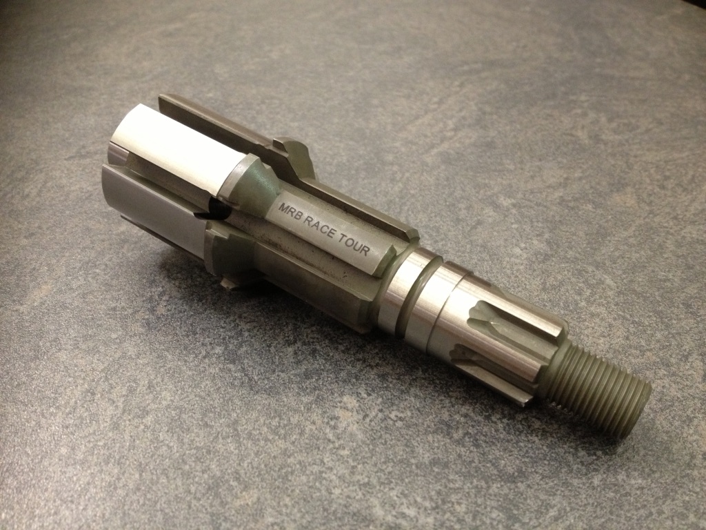
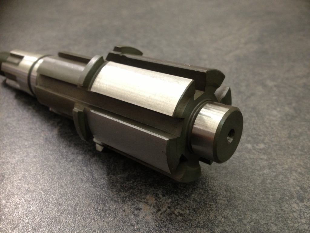
MB have made 2 rear hub bearings over the years. The early ones where made by JBL – original fitment for SIL. But both JBL and SIL bearings are wrong in their machined heights and they tend to stick up higher out of the casing bringing the inside part out towards the rear hub, this makes more room inside the gearbox area and requires a larger gear shim or the special MB shim between the layshaft and bearing. We had it out with the company and gave them drawings on later batches to improve them but the reply was ‘these are exactly the same as the original SIL drawings’ later we found out JBL wasn’t even the manufacturer but just a middle man who couldn’t read a drawing. As usual with Indian manufacturing they put up the price and minimum order quantities so we stopped using this company. These bearings are identified by having a plastic cage for the rollers, the early bearings used the standard rear hub seal with a 32mm inner diameter, the later version used a different diameter 31mm seal so beware if your reusing one – it’s worth checking the sizes if reordering rear hub seals. Both are marked with MBD Race-Tour. MB’s new rear hub bearing comes with a seal or without a seal. These are marked with MB Race-Tour but has a steel cage as per original. Aiming at Innocenti’s spec’s, but we’ve redesigned various areas to improve the bearing so fitting is better with better tapers to aid fitting. The large part was increased to tighten up worn casings. One mod we’ve done is add an O ring groove to the bearing to help seal between the casing and bearing or hold silicone in the groove. This bearing fits slightly in towards the gearbox so the gear shim is usually a thinner version. Where as the older MB and SIL bearings faced away form the gearbox and usually required a thicker shim.
FITTING A REAR HUB BEARING
First check the bearing doesn’t just drop into a cold casing, the bearing needs to be tight with the engine cold. It’s always best to warm the casing to expand it, any heat helps, certainly better than a freezing cold engine, don’t do anything to the bearing it’s self – fit it at room temperature. With a warm engine, smear silicone around the two outer fitting faces on the bearing and casing. Don’t smear it into the ball bearings. With a warm casing the bearing should drop into a casing. Tap it home gentle with a small hammer hitting the outside of the bearing on opposite sides, don’t hit the inner race! But ideally a bearing pulling tool should be used to fit a bearing. Silicone should bulge out around the outside of the bearing, smear it around the out side of the bearing and rub it into the outer hole as the casing is usually much wider than the bearing size. Then wipe the area so it’s nice and clean.
When the bearing is fitted, oil the bearing balls and the inner face where the seal inner face will go. Fit the seal, the outer edge needs to be dry so it locks in place and won’t spin. If a seal is slightly loose in the bearing, smear some loctite on the outer edge when fitting, don’t let any loctite into the bearing. Some inner faces of bearings don’t have much of a chamfer. As you slowly fit the seal make sure the inner face is pushed over the inner bearing ring. Use your nail or a very thin blunt tool to help the delicate inner seal face go over the bearings inner face.
We have addressed this with a bigger taper on the later MB bearings. Do it wrong and oil can leak into the brake shoes from either – around the outside of the bearing or the inner seal lip.
BUT the major cause of oil leaking into the shoe area is not the bearing seal but the O ring fitted to the layshaft………. always fit a new O ring to a layshaft, more on that later!
I always smear silicone around the outer edge of the seal as well, but not where the bearing turns. If there is enough silicone used when you fit the plates it will seal between the plates, seal and bearing and it should never leak. You may need another squirt and smear of silicone on bearings that stick up high out of the casing for the plates to seal.
Use correct length hub plate studs, loctite them in place. I use 6mm nyloc nuts with no washers compared to original plain nut and wavy washers. Whatever you use don’t over tight them – just nip them up! If using the tall nuts loctite them as they can come off, where as nylocs don’t if the nylon of the nut hits the stud and the studs are in tight these won’t come loose.
If the rear hub bearing is a loose fit in the casing when cold then you are in trouble, it will be a toss up between choosing a new casing or using bearing loctite instead of silicone. Unfortunately this is occurring more and more especially with engines rebuilt far too many times, especially if the casing hasn’t been warmed when removing and refitting the bearing in the past. We have addressed this with our MB bearings and made the outer size slightly wider and added a sealing O ring under the bearing which will crush on fitment and if you’re lucky can be fitted dry! MB offer slightly oversized bearings if required if a standard bearing is loose. You can use bearing fit instead of sealer on the outside of a bearing – this will lock up a loose bearing in a casing. Bearings with outer O rings will sit slightly proud and its best to use our bearing fitting tool to pull the bearing in tight, then let the casing cool down before removing the tool.
MB have addressed the problem of rear hub bearings been flush, near flush or sticking up out of the casing and the problem of the shim and rear hub plate bending over. We offer 3 plates in stainless steel, individually or in a kit. These are machined with a flat side or with a varying recess so you can pick a plate that will clamp the bearing tight but without having a big gap where the plate can bow and deform the studs. MBP0470K is flat one side with a recess of 0.3mm on the other side. MBP0471K has a recess of 0.5 – 0.7mm. MBP0472K has a recess of 0.9 – 1.2mm. MBP0477K offers all 3 in a kit. If your building a new engine it’s a total unknown where your bearing will sit, the kit covers all bases.
Whether you use the old method of the thin shim and plate or our new MB method and the plates are secure with a good bearing fitted and sealed we can move on.
Bearings vary in design in their heights. You would think it’s easy to copy such a simple bearing design, but no, manufacturers can’t do such a simple job. They vary where the widest part that fits into the casing. And some are higher than others so some fit near flush and some sit proud. The casing machining can effect the bearing sticking up even if the bearing is as per Innocenti’s design. Genuine Innocenti/Spanish are usually best and sit near flush and when fitting the silly thin shim and rear hub plate they should fit on and off easily. Then there are some which sit around 1-1.6mm proud, if you over tighten the plates the silly little weak designed 4 studs will pull over and makes the plates hard to pull off at a later date. Again MB have addressed this with a new designed rear hub bearing plate design.
Fitting a rear hub bearing isn’t usually hard, it’s not rocket science and doesn’t need a special tool – or does it? Some bearings pull or tap in slightly sideways which can damage the casing. MB have come across a few fitted like this and it’s harder to follow work like this – the cure was a special MB pulling tool. This tool really came into it’s own when fitting the new MB rear hub bearing with special inner O ring. When fitting the bearing the O ring could stop the bearing fully sitting home! The MB pulling (and extracting tool) can pull in dry cold bearings – but it’s best to heat the casing, seal the bearing and casing and pull in the bearing until it locks solid in the casing. Heat can come in various forms, I use a gas welding set when rebuilding an engine. I warm up a bare casing and fit both drive and rear hub bearing at the same time and let the casing cool with the bearings in place. Not every one has access to gas welding equipment. I also use a hot air gun, but takes time to do and again not everyone has these. I’ve also used a gas cooker and you can use boiling water. As long as you get the casing hot enough so you can only just hold it for a split second before it burns you, this is hot enough to expand it so both bearings drop in and you have time to fit and seal both before the casing cools and contracts locking in the bearings.
Bearings are usually the same height in total – 18mm. The fatter part – the top hat shape varies from 6 – 6.50mm which effects the smaller section which fits into the casing. This non perfect design and with copies of the original bearing usually means if a bearing sits flush or near flush to the casing the underside part will be closer to the gearbox tightening up the space. This should make the gearbox need a thinner main gear shim. If you can not get the shim to give clearance with the thinest genuine sized 1.8mm shim then we offer special thinner 1.4 – 1.7mm shims.
If the bearing sits raised and 1.6mm is the most Ive come across then the under side is pulled further away from the gear box. From flush to + 1.6mm! Thats 1.6mm you have to try and work into the gear shimming. If a bearing is raised from the casing then a thicker shim is usually required. If you get to the fattest genuine shim at 2.8mm then an after market 2.9 or 3.00mm maybe required.
We were so fed up with inferior made gear shims from all our suppliers we went and made our own precision hardened gear shims, marked up with MB and the size. Innocenti only offered shims with a 0.2mm increment starting at 1.8 – 2.8mm, we filled in the gaps and did a full selection in 0.1mm increments to get that gearbox just right!
- 1.4mm
- 1.5mm
- 1.6mm
- 1.7mm
- 1.8mm
- 1.9mm
- 2.0mm
- 2.1mm
- 2.2mm
- 2.3mm
- 2.4mm
- 2.5mm
- 2.6mm
- 2.7mm
- 2.8mm
- 2.9mm
- 3.0mm
- Gear shim kit, evens 9 shims 1.4 – 3mm
- Gear shim kit, odds 9 shims 1.5 – 2.9mm
- Gear shim kit, odds and evens 16 shims 1.4 – 3mm
- Gear shim kit, thin 7 shims 1.6 – 2.2mm
- Gear shim kit, thick 8 shims 2.3 – 3mm
If your fitting the fattest shims and your still struggling and you think you have nowhere to go – MB made special packer shims to fit between the layshaft and bearing. We do 3 sizes 0.5mm, 1mm and 1.5mm. These new shims are just a way of taking up slack in the gearbox and you can reduce the thickness of the main gearbox shim. These packer shims can be used to your advantage IF you can’t be bothered to remove and replace the rear hub bearing again. It’s just a case of knocking out the layshaft and fitting one of these packer shims to take up the gap. Let’s say if you’re at 3mm on the large shim and you want some simple adjustment later on in life you can fit a MB layshaft shim. Using a 1mm packer shim will mean the main shim can be reduced to 2mm giving you some adjustment later on in life.
Rear hub bearing heights also dictate where 4th gear sits in relation to 4th gear on the cluster. This is not normally an issue as a 4 speed gearbox has around 3mm up and down movement and nothing locks up. It’s when you use a precision 5 speed gearbox that this height can effect mating gears inline with each other.
LAYSHAFT
There are a few checks we need to do before we fit the layshaft. Take your layshaft and inspect it, you need to make some decisions. There has been a few near death experiences with layshafts snapping! Everyone one has become blinkered in the fact that genuine Innocenti parts are the best! Well one day they may have been, but today these things are over 40 years old and metal does fatigue over time. Add to the fact that a rear hub nut has to be tightened to very high torque figures and also these things are hit with a hammer! The weak point is the layshaft at the bottom of the threads, if this snaps you have milliseconds before the hub falls off and you follow! Today we have addressed this problem and made our own MB Layshaft, these are not a cheap easy part to make, they are a precision part made with many processes but we think are the best available. You have the choice, old or new, The Italians make a layshaft as does SIL the choice is yours……
CHECKING THE LAYSHAFT
Once you have a layshaft you need to check it out. 1st for it’s condition, not only if it’s old but also check new ones. Layshafts are a high wear item, it comes in for some heavy work holding the hub and wheel and all the gear selection jobs the gear box has to do as it spins.
Looking at a second hand layshaft check the condition of threads. Most layshafts have been knocked out with a hammer, this mushrooms the ends of the threads. It may not be obvious, if a nut doesn’t fit try the nut on a rear shocker thread or engine bar, if it fits them, then it’s the layshaft at fault. You can lightly grind the edges of the threads as you turn it to put a taper on it. You can try a die nut but the layshafts are so hard these never cut the threads, you could try a thread file also. Check for obvious splits and cracks in the threaded area. Two areas to inspect is the smooth area where the inner layshaft needle bearings runs, these can be pitted, if they are – they are not easy to mend so scrap it. Check where the larger 1st gear runs, this takes the hammer from the kickstart and does wear away especially if the larger gear shim has been set wrong or the shim has worn.
There have been two types of layshafts – early thick fatter ones and the later thinner types…….. there is no strength difference between the two, both are usable if you want to use them.
Once you have inspected an older layshaft and you think it’s good then as with a new layshaft you need to do more checks………..
-
These visual checks need doing with the layshaft in your hand, if you fit it and find these problems later it’s a pain to start again. Presuming the layshaft is designed and machined right and we – have to have some trust in the manufacturer. The 1st and main part to check is the layshaft height where the gears run, providing you are using a correct matching gearbox that works out to the books then it should match and spin free.
Take the layshaft and fit the 4 loose gears.
-
fit 4th gear, this fits with the raised boss facing up towards the end plate
-
fit 3rd gear, the raised boss fits towards the rear hub
-
fit 2nd gear, the raised boss fits towards the rear hub
-
fit 1st gear the kickstart teeth faces the end plate
Once the gears are fitted they should spin free. They should have very little rock and very importantly the gears should be higher than the layshaft where the large gear shim fits. If the layshaft is higher than the gears and you have definitely got a matched set of gears then either try a different layshaft or very carefully grind the high spots down on each 6 points until the layshaft is below each point as the gears are spun. This area to be ground makes no difference to how the gear box runs. If you fit one with a high layshaft you will never shim up the gearbox as the layshaft locks the gear shim and the 1st gear just spins free. As long as the layshaft is a minimum of say 0.10mm (0.004”) – 0.05mm (0.002”) below the 1st gear you will be able to get the gear shimming correct when you assemble the gears. This depth can be more with no ill effect but if too big the first gear can rock more as ther’s less support where the gear runs. It has also been known that gears can be machined wrong and the gears sit lower than the layshaft, before you go grinding away, maybe try another gear box just to check. We have seen this with new Indian gearboxes and mixed gears especially if a gear comes from a different manufacturer.
So your happy with the layshaft, then move on. Before you fit it you need to fit the gear selector or cruciform, these will also need checking.
CHECKING THE GEAR SELECTOR
As with all parts in the gearbox you can use old and new parts. NOS parts are very limited and vary in price and quality. Forget the rumours, genuine SIL selectors are very good it’s been many years since we’ve had faults with them. We did buy up all the NOS Spanish gear selectors that we could get, again these were very good but ended up been expensive and supplies have dried up. There are also Italian copy selectors around these are ok but again not cheap. MB also make a quality gear selector but supplies have been hard through covid times. With all new selectors they usually come with some slight burrs from machining, these don’t stop function but its worth checking them over and if you have too – clean them off. Obviously if you use a new selector then the dog ends that select inside the internal gears will be square. This doesn’t mean they are perfect, they can move in the heat treating process. I’ve seen real bad ones only contact on three of the 6 dogs/prongs onto a gear when fitted.
In the old days with all gear box rebuilds I would fit the selector on a layshaft then offer up each gear in it’s drive position to see which dog/prong touched. I would then grind the high ones until all 6 touched. It used to be a right pain, but it meant my engines never jumped out of gear even using standard old selector springs. The moment we made our MB stronger selector spring I stopped doing this mod as the spring worked so well. In practice under load the gear lugs would probably hit all 6 lugs on the selector as the selector would deform slightly in it’s spring state.
When it comes to using an old selector you have to look at these dogs/prongs, experience or having a hand full to study will tell you if it’s a decent one to reuse. The larger the dog/prong the better, used ones are usually rounded off or are on a taper. As I have said you can check them and lightly grind them. It has been known to weld the ends and regrind to suit, or just trust the MB selector spring to hold it in place.
Inside where the selector balls run on a new one usually looks rough, you can if you have the right tools lightly polish this area. Personally its a waste of time, look at a used version you can see where the balls run, it is a very fine line showing how little contact there is where the balls run.
If you have a good gear selector make sure it drops loosely down the layshaft. Gear selectors can slightly twist in manufacturing or over time in sheds. The selector should slide freely in all 6 positions, sometimes it maybe free in only a few positions, it’s worth a try to find the best position. It doesn’t matter if the selector feels too free and sloppy under load it works perfect. Any high spots, clean up so it slides free.
GEAR SELECTOR SPRING
There has only ever been a standard spring from the factory, these are quite weak by comparison these days. Add to the fact that old springs are now coil bound as they have been under compression for so many years. Add into the equation most of the after market springs from India are at different lengths and strength. In history gears jumping out has been blamed on a bad gear selector. Most of the time cables are the culprit, but it’s been found the springs have been far too weak to do the job. Fed up with inferior springs MB made a stronger selector spring and suddenly gear jumping was a thing of the past. The down side is, some complained gear selection was difficult. But every time we saw this complaint these people had a bad cable/linkage set up and of course it’s easier to blame MB on a little spring. Our advise is fit this little simple spring to your motor and it will work for years. But always use a nylon lined friction free cables these are a wonder to gear selection. We also remake an improved standard gear selector spring for those that want them, these work perfect with our MB gear crusiforms.
GEAR SELECTOR BALLS
These are just standard ball bearings. I’ve never seen gear selector balls wear. Of course ball bearings can break up, but in a Lambretta engine with oil used I’ve never seen it. So check that the chrome surface is still good with no rust. If in doubt change them they cost nothing. Make sure the balls drop in through the hole in the layshaft and that they are free running and are not tight. If they are tight even on a new layshaft you can lightly grind out the hole with a small grinding stone to free up the balls. It may just be a burr from machining that needs cleaning up!
FITTING THE GEAR SELECTOR, BALLS AND SPRING
It’s impossible to fit the layshaft into the rear hub bearing then fit the gear selector so don’t try. You have to fit the gear selector first onto the layshaft before the layshaft is fitted into the rear hub bearing.
Fitting the gear selector is unbelievably simple but people make a mountain out of a mole hill as usual on such simple things. Get it right and it’s an easy job – yes ok get it wrong and the balls fly off everywhere!
The gear selector can only fit and work one way, that is with the 6 selector prongs facing away from the rear hub bearing.
To fit the gear selector, you need the layshaft, the gear selector, the spring and the 2 ball bearings.
Take the layshaft in one hand, drop the selector down the layshaft from the needle roller end so the 6 stuck out prongs are last. Make sure the selector drops low enough to expose the hole where the spring fits. Drop one ball into the hole and let it drop through, make sure you have one finger on the other side to stop it falling straight through. Next add the spring then the last ball, push both balls inwards with a thumb and forefinger, as your doing that push up the selector holding the balls in place as all 6 prongs have a taper to help the balls fit, push a little further and the balls and spring will click and the selector will stay in position. Don’t worry about sliding the selector up and down, it will. If you move the selector so the dogs come flush or near flush with the end of the layshaft where the large shim would be – this will be 1st gear position, it’s best at this point to move it back slowly one position which will be neutral.
Some gear selectors have two tapers on the opposite side to each other on the rear hub bearing side – but not all of them. If your selector has these they are even easier to fit. Line up the selector so the the tapers are inline with the hole for the spring and balls. Put the selector on a bench, prongs down, fit the layshaft correctly, fit the balls and spring, hold them in place with finger and thumb then push down the layshaft – easy!
Some make tools to hold the balls in place – oh really! Not needed at all.
To check the gear selector and gearbox is good in terms of gear selection in neutral. Fit the gears in the correct order. Hold the layshaft so the threads point directly towards the floor and the 1st gear is upper most. Spin 1st gear – you are listening for signs of clicking and looking for lifting as the gear spins over the gear selector dogs. Do the same with the 2nd gear. This will show if the hole in the layshaft is at the correct height. It will show if the gear selector is at its correct height and that the neutral position is correct were the selector balls run. And it will show that 1st and 2nd gears are correct. This procedure is a must, if you have to do this with the layshaft fitted and you find a fault it’s harder to do later on. A very fine click is quite normal, you can do some light grinding to help out if there are high tight spots which you can find by putting marking out fluid or marker pen on where parts can touch. Also beware most gears have a little click as the gear gear dogs run over the gear selector grooves on the layshaft.
FITTING THE LAYSHAFT O RING
With the selector fitted to the layshaft it’s now time to get cracking on the rebuild. Before the layshaft is fitted into the rear hub bearing you need to fit a new O ring, never use old ones they tend to leak oil into the brake shoes. First check there are no sharp edges or burrs and clean them off before you fit the O ring. Smear some loctite into the groove, not too much, smear it around with your finger, then gently pull the O ring over the layshaft threads and splined area, basically like rolling on a condom! I know! But you know what I mean. When the O ring drops into the groove there should be enough loctite in the groove to smear around the O ring so it’s wet and on the metal part that fits into the bearing, but not too much so it can drip into the bearing balls. Make sure the inside of the bearing is wiped dry before you fit the layshaft. (On extreme leaking circumstances you can use a instant gasket sealer). Offer the layshaft into the bearing………
You have a couple of ways to fit the bearing
-
hit it in position with a copper/alloy/soft hammer
-
pull it in position using the MB puller or something similar
If you hit the layshaft in with a hammer, it may well push the rear hub bearing out of place, so it’s not the best way to fit the layshaft. The best way is to use our special layshaft pulling sleeve, it is designed to work in two parts. First part. Hold the pulling sleeve tool with a 30mm spanner then use a 27mm spanner on the nut that comes with the tool. Tighten the nut fully until the layshaft is in position, this draws the layshaft in most of the way. It will then lock up and needs undoing and removing and turning around and tightening up again. Once it’s locked into position leave the tool on until the gearbox is finished – if you don’t you could have trouble later shimming the gearbox!
Most layshaft/rear hub bearing tolerances mean the layshaft is tight going into the bearing. The difference between a tight fit and a loose fit is only a few tenths of a thousands of an inch – absolutely nothing! A loose layshaft with the loctite O ring method will lock solid. We had one that would push in and pull out by hand, with loctite it was a two man job to get it out!
SETTING UP THE GEAR SELECTOR SHAFT, WISH BONE AND GEAR ARM
With the layshaft fitted the hardest part of a gearbox rebuild and often over looked until the end is getting the wishbone and gear selector in the correct position on their splines.
This is the method to assemble the wishbone and arm.
But first you need to check some things out.
-
Wish bone condition
-
Pawls (swivels)
-
Gear selector shaft
-
Gear selector arm
WISHBONE CONDITION
Most wishbones look crap, they are a rough cast steel item and old ones are usually rusty. It does not matter, these can be cleaned up easily and reused. New SIL ones look much worse but are still useable, beware of some aftermarket Indian wishbones, you may as well bin them and use an old one. Obviously you need to check the condition of the wishbone to see if it is bent. You need to check out the condition of the pawls, these do wear and if not replaced it doesn’t matter how good all your linkages are you will always feel play in the headset. Replacing with new ones doesn’t always work, most new ones have wobble when fitted even if using a new wishbone, it’s usually the wishbone bored out too large! If your going to use the original pawls then be careful removing and refitting the silly little 5mm E clip.
The best cure is to drill out the wishbone to 5.5mm, chamfer each end and fit our MB over sized wishbone pawls and make sure they spin free if not run the drill up and down until they are free. This gets rid of any movement starting right at the simple basics from the beginning.
Grease the pawls on the straight section. Pick the gear arm/shaft arrangement that you want to use. If your using the Li type then you can assemble the shaft wishbone arrangement and fit the gear arm afterwards, this makes this version easier to assemble. The problem is getting the Gp gear arm and shaft and wishbone in the correct position so when the gearbox is finally finished and all the linkages are connected every thing works!
To do this you need to get the gear selector Cruciform into 2nd gear position. If you have kept the selector in the neutral position then push it back one click towards the rear hub bearing. If you’re not sure – pull the selector out away from the bearing until the prongs are level with the end of the layshaft. Push it back one click which is neutral and back one more which is second.
Time now to fit the gear arm, I prefer our Gp type with the stud conversion. You can use the Li type but follow the instructions already talked about. Next choose the correct gear arm O ring, these can be changed. Standard uses a 12 x 2.5mm, sometimes these can leak so we offer 2 over sized MB versions 12 x 2.75mm and 12 x 3mm.
Which one to use comes down to experience. The easy way to check – is fit the O ring first into the recess where the arm fits in the casing. The recess can vary in diameter, the normal standard one usually fits fine and should be a push fit into the recess, if it looks loose in the recess try the oversized 3mm O ring. When the shaft is fitted into the bush it should be tight as it’s pushed right to the bottom as it pushes into the O ring to seal. Too tight and you will have to hammer the shaft in place, this is fine but only hammer the center of the shaft where the machine counter bore is, otherwise you will bend the arm. With a dry O ring the arm can be too tight affecting gear selection – grease it and it will turn free and it needs to be free – so always grease the arm, shaft and O ring. If the shaft is too tight with a 3mm O ring and too loose with a 2.5mm version, then we offer a 2.75mm version to help. The gear selector arm bush needs to be perfect so when the arm is fitted there’s little side rock movement, it also needs to be near flush with the casing so the O ring sits right.
Once you’ve selected the correct O ring. Take the Gp arm, fit a 12 x 1mm shim on the arm, then the O ring. With the arm greased offer it down the bush. Here’s where it gets a little bit complicated.
It’s a case of juggling the wishbone into position and pushing the gear arm into the correct position. But whilst your at it, you’ve got to fit the shim between the wishbone and the casing. Normally you only use a 12 x 1mm shim, but gaps do alter and sometimes you need to add an extra shim or thick washer.
Grease a 12mm shim to the wishbone to hold it and wiggle the wishbone and pawls into the gear selector groove. Check the selector is in 2nd gear, drop the gear arm into the bush with the shim and O ring fitted, remember to grease them. As the arm drops through the bush make sure it doesn’t knock off the shim greased to the wishbone. The arm should reasonably easy fit into the wishbone splines BUT as it’s fitting in make sure the arm is 90 degrees to the side casing gasket face or as near as dam it.
Fit the gear selector arm in 2nd gear so its 90 degrees to the casing
This is the perfect position to set up the gearbox. When you’re happy with the positioning, tap the arm fully home and hold it down as the O ring can push it back up and the arm needs to be pushed in as far as it will go or it will leak. Fit a screw into the wishbone, this screw is normally a 6 x 20mm with a 9mm hex head, these are not great to use. I use a 6 x 20/25mm domed allen cap head, a high tensile one is best. The reason for the domed head or the 9mm head is – in 1st gear it doesn’t foul the casing. A normal 10mm head or allen cap can hit the casing. Fit the screw with a strong spring washer into the wishbone and tighten it up, as you’re doing that use a screwdriver under the wishbone to lift the wishbone up and keep the pressure on the gear arm going down, then nip up the screw. Once this is done if there is a gap and up and down movement with the wishbone and the upper part of the casing with the shim, then add another shim or a 12mm front hub locating washer. If you know where to grind you could grind the recess where the screw fits on the selector arm to let the wishbone rise and then only use one 12mm shim, but be careful the wishbone doesn’t go too far to tighten up the pawls in the selector. There should be very little up and down movement but it should not be too tight – remember everything needs to be finger tight otherwise the whole gear selection will be hard at the handlebars. If you are happy with the up and down movement and the wishbone/pawls are free and everything spins and moves and selector in the gear positions by hand.
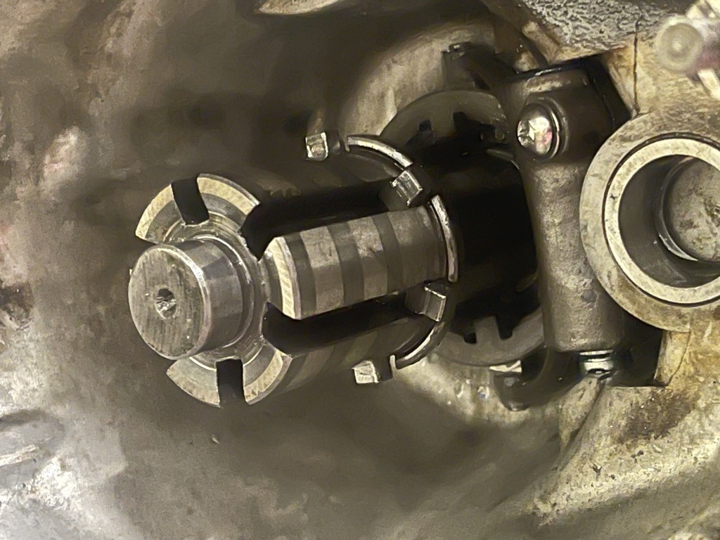
Before the screw is locked in position, move the selector arm to push the gear selector down into top gear which is 4th or 5th it doesn’t matter. The selector should drop down and hit the rear hub bearing, if you look closely the 2 gear selector balls look like they will pop out – they won’t! Next drop top gear down the correct way up. Check the gear selector prongs are level with the gear dogs, if the selector is raised it could be the wishbone hitting the casing forcing the selector away from gear location. Sometimes you can see polished marks on the casing top or bottom or both. If this is the case the wishbone needs removing and the area thats touching needs grinding away. Once done refit and try top gear positioning again. If all is good put a bit of loctite on the screw and set up the wishbone, shim and gear arm and tighten up.
If you have done it correctly you’re ready to assembly the gears. This is always best with the engine on it’s side, so if it’s a full bike be prepared to lay the Scooter over on it’s side.
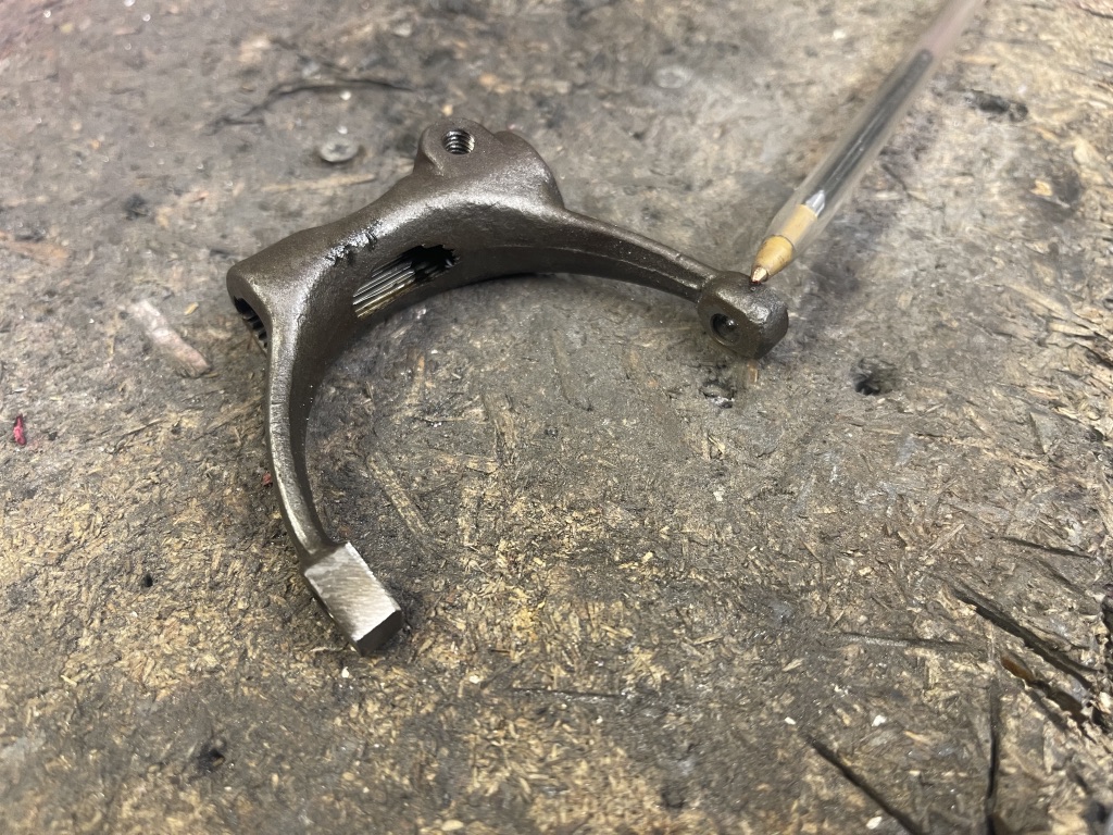
This was a faulty wishbone, which had been machined on the wrong side which left a big chunk of metal touching the casing holding off top gear from sitting correctly and the bike jumped out of top gear. The bit with the pen is wrong the other end has been ground down to clear the casing
With the selector correctly fitted the prongs sit right down which can be seen it runs in the area where the gears run, plus fit the gear to check
FITTING THE GEARS AND GEAR CLUSTER INPUT SHAFT
If you was to believe the manuals you would go into just fitting the gears and cluster, yeah great in that untouched engine. Presuming we are overhauling a gearbox with some new parts or we are building that bitza gearbox. You can’t just presume it all fits…….
Following the manual we have you fit the gears and cluster correctly and fit the end plate to just check out the shimming. Of course you can do this but when you hit a snag it’s all got to come apart, again and again until you find the fault. This method is a little long winded but it will find any snag easier than any other method.
END PLATE
Before the gears can be looked at, the endplate needs to be overhauled and checked out. There are 2 types – the smaller Li, Tv, Sx that uses the adjustable kickstart ramp on the side casing cover and the larger Gp version where the kickstart pin acts on the endplate and has no adjustment.
Whats best? The Gp version is simple but I doubt it is best, the ramp can wear and there’s no adjustment on the kickstart lever. And this type can eventually help loosen off the end plate, but with a good one built correctly they are perfectly fine and the one I mainly use. The smaller type offer no problems apart from wear. The hard part is to see the wear, it’s near impossible without comparing to new parts. On the inside face where the large gear shim fits wears the most, it’s obvious when you see it, the face is all shinny and ripped up. If this area is worn it’s just a case of fit a thicker shim to take up the play, these days with the oversized shims it means any plate can be used.
With Gp kickstart ramps you won’t know how it is machined until the whole engine is assembled and you put pressure on the kickstart lever. It’s usual for the kickstart lever to have a lot of travel before it engages 1st gear and the kickstart is near the floor. No one has addressed this problem, except us with our adjustable kickstart lever. But even with these its not perfect – but read at the end to adjust this issue.
So we have to work with what we have, I’ve already pointed out end plates vary from each casing and how to address it, presuming we have a good end plate that fits the 6 studs and dowels. Always change the end plate ball bearing, these are found most places, you can use a named brand bearing or we make our own. It’s nothing special but is part of our RT engine bearing range that we have made. For the cost, change it – if you’re in doubt to it’s condition or the mileage it’s done. These do break up and wear over time especially if the crown wheel has been prised into position over tightening the chain – so just change it. If the circlip is good you can reuse it or use a new 42mm circlip.
- TOP TIP – End plate roller bearings can be up or down in the area its knocked into. If it is down towards the hub and you set up the crown wheel to drive sprocket and the bearing moves in a hot engine you have lost your settings and chains will wear! Some circlips are ticker than others and the groove can also alter so theres more movement. I use loctite on the outer edge that presses into the end plate and either gently knock in the bearing until the circlip just fits, or knock it in, fit the circlip then gently knock the bearing tight up against the circlip. This sets the area for the cluster (better for 5 speeds) and sets the crown wheel height fixed.
Always look at the outer bearing bush in the end plate. This little item can be the culprit of a rocking rear wheel. It’s near impossible to measure or look and see if it’s good or not good. If the engine has been stripped and you found the layshaft bearing race was pitted and your changing the layshaft then change the outer bearing bush. If the old layshaft needle bearing was broken up change the outer bearing bush! When fitting the outer bush loctite it in place. With the end plate overhauled you can start the gearbox for real. MB make precision outer bushes to stop this rock. We also make our own needle bearing or offer branded bearings.
FITTING THE GEAR CLUSTER
You’ve got the layshaft fitted in tight in the rear hub bearing, next you fit the gear cluster. Start by fitting the needle roller bearing for now do it dry it makes no difference. Fit the cluster needle bearing shim to the cluster with a bit of grease, these are all one size they hardly ever fail and stands out if it has wear marks. Fit the cluster and shim into the needle bearing. Don’t fit any gears.
Drop the endplate onto the cluster, as I’ve said it should be an easy push down feel or just a light tap down. Depending on if your using studs or screws fit 4 nuts or screws and washers, no need to fit all 6, fit the 2 towards the crank and the 2 towards the rear of the engine. And tighten the end plate down by nipping the fasteners, no need to torque them down at this point. If the cluster is loose in the bearing you can pull it up by hand and the cluster will spin. If it’s tight you need to fit your spider and nut and tighten it. As this pulls the cluster away from the needle roller bearing in the casing and pulls it tight up against the end plate ball bearing which is the correct datum point for the cluster and the gearbox rebuild. Ideally with this done the cluster spins easily by finger and thumb. If it’s tight something needs inspecting. Really all it could be is the outer cluster bearing is not knocked in far enough or for some reason, or it’s not fitted correctly or the cluster is machined wrong so try removing the shim between the cluster and the casing. This usually cures the 5 speeds and after market close ratio gear boxes.
Spin the layshaft just to make sure it is also free. Once your happy remove the end plate, fit the layshaft needle roller bearing shim and the needle roller bearing, refit the end plate and tighten it. Once tightened spin the layshaft again with the tightening tool at the back of the engine on the hub side, the layshaft should spin. If it doesn’t and it’s lock up, you know it is not the cluster so suspect the layshaft needle/shim area. It has been known the area of the layshaft is machined wrong, removing the shim gives an extra 1mm free movement so the layshaft should spin free.
- TOP TIP – Life will be a lot easier on gearbox rebuild if the cluster moves freely in the end plate roller bearing. If you’re having a nightmare setting up a gearbox and you have to hammer and extract the end plate on and off each time. It’s best to polish the area on the cluster that fits in the bearing. This can be done by hand or easier if the cluster can be mounted in a lathe or pillar drill and carefully polish the area with emery to give a perfect snug fit that moves in and out by hand. Don’t try to bore out the inner bearing area.
FITTING THE LOOSE GEARS
With the cluster spinning nice remove the end plate, here you will thank me for the time you spent making the cluster pin free in the end plate. You should be able to hand pull off the end plate, or use a screw driver against the casing to prise it clear, or use the end plate T bar extractor tools.
With the end plate off, it’s time to fit the loose gears. Leave the cluster in place, fit the 4th gear, raised edge upwards (see later for a 5 speed but it’s the same) spin the cluster and make sure the cluster and gear spin ok, then rock the cluster back and forth to see how much back lash is in the gear. How much back lash comes down to experience! Lets say back lash is something like 0.5mm any more would be too much, down to 0.10mm should be ok but no back lash could be a problem in locking up. You do get some gears which look good and count correct but as you turn the cluster most of the gear mesh and spin but towards the end of full revolution it can lock tight then spin free again. If you have checked and rechecked and everything on the gear box says it’s correct it could be the centers of the rear hub bearing to the cluster centers – these can vary slightly! You could if you really have to use grinding paste to help out but I’ve never had to do this.
If the gear does not spin easy and tends to lock up a bit or has too much back lash then recheck the gear is correct in the diameter and number of teeth! Use the gear arm to move the selector into top gear position, this will lock the selector up against the rear hub bearing so it can not jump out of gear towards the bearing! Look at the gear selector gear dogs they should be in line mating together with the loose gear dogs, if it’s not the top gear is upside down! Or the wishbone is hitting against the casing, if the wishbone is hitting and it’s really hard to see by eye, sometimes a feeler gauge is needed to see if there is a gap between the casing and wishbone.
This is the same method for 4th, 3rd and 2nd gear – drop the gear onto the layshaft – push the selector into position and spin the cluster. If it’s a miss matched gearbox or even a new SIL gearbox or a series of ‘on paper’ correct Italian/Spanish gears take your time it will pay later. Some gears will work miss matched and some will not!
When your happy all gears spin free with not to much back lash you can safely say you could have a good gearbox!
FITTING THE END PLATE
It’s now time to start the gear shimming. Remove the cluster and refit the gears in the correct position. Fit the small thin layshaft shim on the layshaft and then the layshaft needle bearing. The shim is one size and is not adjustable. You can use old needle bearings but for the money if your not sure just replace it.
The easy start to the final assembling of the gearbox. Oil the crusiform so it runs down the layshaft and gears, this stops any friction with clean dry gears. Fit a 2mm large shim. I say 2mm as it makes working out what actual shim you need easier – easy maths!
Fit the end plate and tighten it down only using the 4 holes as before. If the layshaft and gears are tight or locks up and the procedure you have followed is still working correct, then you need a thinner big gear shim.
We offer our own smaller shims 1.4, 1.5, 1.6, 1.7, 1.8, 1.9mm. If it super tight – go for the thinest shim, if it just moves by gripping the cluster by hand then go one or two sizes down.
You are looking for a clearance of 0.076mm to 0.304mm (0.003” to 0.012′)
This is the clearance between the gearbox which is now the big shim and the endplate. The gearbox and shim are precision machined parts! Where the end plate is not. The endplate is machined and the area where the shim spins can wear. And sometimes it can wear to one side making checking the gap even harder to do. The gap you need to measure is the gap between the large gear shim and the end plate, this is measured using a feeler gauge. The best feeler gauges are the ones with a pre-made kink in them. Pick a 0.304mm (.012”) feeler gauge try to wiggle the gauge in between the shim and endplate, it should fit in a good 8-10mm. If it doesn’t go in, pick a smaller shim until it fits. Move the gauge up and down and around the big shim and the end plate. Ideally it should be slightly tight but loose at the same time. It’s like setting the points gap but harder as your working down into the box. This is why the bent gauges are better, your not working against bending a straight gauge which gives a false reading.
If you’ve fitted the 2mm shim and the gap is bigger than the 0.304mm (0.012”) gauge then you can easily add gauges together to where you can not get anymore gauges in the gap. Remove the gauges and add them up, then remove from your figure the gap required for the gearbox to spin free. The figure left is the extra that needs adding to the 2mm shim.
If your figure works out at say 0.6mm then 0.6mm (feeler size) + 2.00mm (shim) – 0.30mm (end plate clearance) = a 2.3mm shim!
Remove the endplate, swap the shim from 2.00mm to 2.3mm, retighten the gearbox and check the gap and see if the layshaft and gears spin free. If it does your nearly there……… one last check is to get a bent instrument, one of those hooked picking tools works fine, hook it underneath the first gear then try to pull up and push the first gear to rock it. If the first gear rises up and down but the shimming seems correct something is wrong! So re check things out.
Personally I work a bit tighter than the factor settings, if I can get the tolerance down in size but can easily turn the layshaft by hand – I am happy. The end plate gap could be as small as 0.001” – 0.01mm.
It’s like this – the gearbox is bathed in oil, it gets hot but not that hot in reality. If every thing turns free by hand and there is no up and down movement in the 1st gear then all that can happen over time is things can wear over hundreds of miles, if this happens you can increase the gear shim on the next rebuild if nothing is broken or worm out. BUT if your working to the last gear shim sizes where can you go?
The tighter the better but it must spin free! There is less chance of anything jumping out of gear, gear selection is easy, no gearbox rattle from the first gear and gears don’t wear on the layshaft as everything is held tight together – this works all the time. This is all providing the gears spin by hand proving it’s not too tight.
Next remove the end plate and fit the cluster, then refit the end plate and tighten the end plate – fit the spider and nip that up. Again the cluster should spin the gears and everything should be free! Yes it’s a long winded way but it saves the end plate on and off and on and off trying this and that and getting no where!
Now for the complications of which there are many……..
Endplates can be worn or machined offset where the big gear shim works, meaning the gauge may only fit in one side. You could have a really big gap one side and tight the other side. You could get a gauge in but the gears don’t turn free. You may get a feeler gauge in and there seems to be lots of play but the rear of the layshaft is tight and you can’t get to it. You can remove the end plate, ink it and fit and remove to see if a high spot shows up which you could hand grind. So it comes down to that up the and down technique I use. If you use this method the large gear shim should turn as you turn the gearbox, if it looks tight, spin the gearbox and push the big shim with your finger it should be free. At this point make sure both sides of the shim are oiled. It’s quite common to have to mount the end plate in a milling machine upside down and remachine to find the high spot!
If you get to a point where you’ve fitted a 3mm gear shim and you still have play, then what to do? MB make the special shims 0.5, 1, 1.5mm to fit between the layshaft and the rear hub bearing, these lift the layshaft up towards the end plate so reducing the gear shim size. Fitting these shims does not effect gear selection, all it could do is make gear teeth move out of line to the gears on the cluster, but the standard 4 gear gearbox can take this no problem (be careful with 5 speeds).
If for some reason even with a thin 1.4 – 1.8mm shim that the gears lock up, you can machine the layshaft in a lathe where it butts up against the bearing, again it’s like adding a shim in the same place, it does the job but gears can be slightly offset. We’ve come across these new super engine casings where layshafts have needed to be machined to get clearance!
Once you are finally happy that everything turns and is free, it’s time to finally finish it off. Remove the end plate. Oil down between the gears and layshaft so oil gets around the layshaft and into the gear selector balls. Oil where the layshaft shim fits and oil the needle roller bearing. I prefer to grease the gear cluster needle bearing and both sides of the cluster shim. Refit the endplate, what ever fastener arrangement you’re using make sure all the threads are clean and free from oil. Use loctite on the threads to stop them vibrating loose. Again use the 4 fastener method and recheck everything spins correctly, add the last two fasteners and tighten down
- nut 9.8 – 11.8Nm
- screw 14 – 17Nm
Again recheck everything spins free! Finally oil the gear cluster ball bearing and thats it – your done!
I’ve loss track how many engines I have built and have never broken a gear or had gears jump out and have never had a gearbox return from a customer. Yes it takes time, yes it sounds very long winded but if you do it right its worth it in the end. Pointless trying to get a 40 brake horse power engine then have a gearbox set up wrong.
SETTING UP – GP END PLATES
Once the gearbox is assembled you can fit the assembled crankcase side and you can operate the lever to see how far it takes to engage the kickstart teeth and turn the gears. Usually on a GP the lever goes a long way down making it hard to start an engine off the stand. Kickstart shafts vary as well and some splines will vary so one is good and one isn’t. Using our MB kickstart shaft helps if the splines are out but it doesn’t really cure a bad end plate GP ramp.
The cure is – you can adjust this by grinding the slope on the end plate. With a perfectly set up gearbox with the end plate bolted tight, with an assembled crankcase side, fit this to the engine with the gasket with 4 equally spaced nuts. Operate the kickstart lever and note how far it travels until it engages. You need to hold the layshaft so you can feel things turning.
Now again more long winded work – remove the side cover, remove the end plate. There is a high part, then a slope, then theres a low part. It’s the slope that needs grinding away, this controls when the kickstart teeth engages 1st gear. Try grinding 6mm off at a time, until it engages earlier, you can increase the angle of the slope so the kickstart reference pin moves faster so it engages quicker – meaning the kickstart lever will only move a small amount to engage. Be careful once done its hard to add metal back on, little at a time – well worth it long term. If you are going down this route, if you select 1st gear you can feel the gears turning when working the kickstart lever. One trick is to turn the layshaft and 1st gear in the opposite direction – if the 1st gear grabs the kickstart plunger engages you have gone too far. Going down this route means each time the end plate needs cleaning the bearing parts need blanking off and the slope needs grinding which is a messy job! Ideally an engine fitted in the frame would have the kickstart move a small amount so it engages correctly and turns the engine over.
SUMING UP
Once you have run your engine and the gearbox is noisy then you may have to re address it. Or over time clicking or rattling noises can appear! This could be a number of things. It’s known for the odd gear tooth or cluster tooth to chip off, this will give a click or clicks. Loose gear shimming gives a click and a rattle. Incorrectly set kickstarts will have a constant click as the kickstart teeth click on each tooth. Rocking the rear wheel will find any play in the layshaft needle bearing area and it goes on! Follow the above and non of these should happen.
I’d like to say thats it! But knowing Lambrettas there will be some oddball occurrence turning up one day that I have never seen before!
MB 5 SPEED EXTRAS
The MB 5 speed gearbox really is a work of art. But there shouldn’t really be anything any harder to do in setting them up, compared to the 4 speed versions. You just need a little more patience and checks as already explained.
If you assemble it correctly the gears and clutch handlebar gear change will all work as per standard.
To get the extra 5th gear into the limited space between the rear hub bearing and the end plate we designed the gear cluster with a solid shaft with 1st gear on, then 2nd-5th 4 gears are pressed on the keyed cluster shaft and loctited in place – solid!
This means there is hardly any gap between each gear like on a standard 4 speed. A standard 4th speed gearbox cluster is machined by a method – where the gears are cut by pushing the metal out and a gap is needed to remove the metal cut from the gear. The MB 5 speed uses these gaps in a standard cluster and adds them up to find the extra gear, so gear widths are the same as a standard 4 speed gearbox but with improved metal and stronger teeth. To gain a little more space we have removed the shim on the bottom of the cluster so……… DONT FIT IT.
This now means with the gear cluster fitted and tightened up into the end plate the cluster has only a little bit of movement up and down otherwise the loose gears on the layshaft will touch the gears on the cluster.
To check this out and under stand – with the layshaft in your hand, assemble the 5 loose gears on your layshaft in the correct order (these should be marked on each gear BUT the odd gear has slipped through marked wrong.
To fit the gears correctly……… fit the oil groove cut outs on the gears towards the hub. Then offer up the 5 speed cluster so all 5 loose gears are perfectly inline with the cluster. No gear should be miss matched, they should all equally line up perfectly. Move the cluster or layshaft slightly up or down and you will see in around 0.5mm the gear edges will touch! This goes back to casings and parts varying! The gearbox datum point will be when the cluster is tightened into the end plate ball bearing by the spider.
I’ve explained the layshaft can be up or down depending on the rear hub bearing position in the casing or the casing machining or the height of the layshaft. You can lift the layshaft with a shim and you can reduce the layshaft with some machining or playing with a different hub bearing.
Next as a check – fit our MB 5 speed gear selector to the layshaft. Our selectors have two tapers on the opposite side to each other on the rear hub bearing side to make fitting the selector easier. Line up the selector so the the tapers are inline with the hole for the spring and balls. Put the selector on a bench, prongs down, fit the layshaft correctly, fit the balls and spring, hold them in place with finger and thumb then push down the layshaft and pop, the balls will click in position – easy! No need for any silly tools here!
Now as another check, fit the 5th gear – with the oil grooves to the hub side. Now fit 4th and then move the selector into 4th position and check the dog of the selector and the dog of the gears are perfectly in line against each other. You can not do this in 5th as that is stopped in position by the rear hub bearing. Do the same for 3rd, 2nd and 1st. If all dogs line up then select neutral, with the layshaft thread down and 1st gear up, the gears should all spin free with no clicking.
Now time to fit the box, but do this method – it will save some stress if things are not right.
- Fit the cluster (no shim and no loose gears) and tighten the endplate, fit a clutch shim and clutch spider and tighten the nut – the cluster should spin free! Remove the spider. The cluster should be slightly loose in the end plate roller bearing and should be easy to pull the cluster up and down, if this is the case, from the straight edge off the side casing face take a measurement with a vernier off the top of the cluster where the threads are in its pulled tight position. This can be important to set up the gearbox.
- Remove the end plate and cluster. Fit the layshaft and tighten it in the rear hub bearing. Fit the 5 gears correctly, fit the layshaft needle and small shim, fit the end plate but don’t fit the cluster. Then go through shimming up the big gearbox shim and make sure it all spins free.
- If both cluster and layshaft/gears are free separately then remove 1st – 4th gears, with the hub towards the floor fit the cluster and needle cage and lift it by hand to the position where it will end up once tightened by the spider nut. Now check that 5th loose gear and the 5th gear on the cluster are directly inline. If not gears may click or lock on full assembly. If the gears are out of line there is very little that can be done because of the restraints of the various machined areas from the various factories. (A) If the the cluster is higher, then a shim/s needs fitting between the cluster and end plate roller bearing. (B) if the cluster is below 5th gear, then either a different height rear hub bearing can be fitted, or a shim under the rear hub bearing before it’s fitted, or the layshaft can be machined on the face that butts up against the rear hub bearing.
Now if we’ve got all our calculations correct you should be able to fit the cluster and gears and everything should work without locking up or have a clicking noise when the cluster is turned. But as we’ve taken an average of all gearboxes/casings and parts included in a gearbox rebuild the chances are someone will have an adjustment issue at sometime. Please don’t be afraid to ask ………but make sure you have read the main article first so you know what you are doing. Or have us fit the gearbox for you and have a piece on mind it is done correctly.
Some MB5’s have fitted just like standard gearbox with a 2 – 2.3mm shim in Italian, Spanish and SIL engines. With oddball engines with different rear hub bearings and miss matched end plates, some have needed thinner shims 1.4 – 1.9mm, usually caused by the rear hub bearing height which vary from manufacturers.
TIP – If you have a problem, probably the best way to check alignment especially if the gears lock or click is to drill the gearbox endplate between the roller bearing and the layshaft. 13-15mm should be fine to see through with a torch – start by drilling with say a 3mm pilot drill, then 8mm then the larger one. This will allow you to see if the 5th loose gear is inline, high or low compared to the 5th gear on the cluster. Fit the 5th loose gear to the layshaft – fit the cluster – tighten the end plate and tighten the spider to the cluster. Look through the drilled hole to see the positioning height of the 5th gear to the cluster gear, it needs to be perfectly inline + or – say 0.2mm. If 5th gear is in line then all the other gears should be inline.
If you’re happy at this point, strip and rebuild as normal always checking for free movement with no clicks or tight spots. The final check will be when all gear box parts are fitted with a torqued end plate and spider fitted. Tightening the spider will lift the cluster into position, this final operation can again lock the gearbox or leave it clicking or tighter than the early test builds. The chances are you may need the special shims that come with the gearbox to force the cluster away from the spider and reducing the up and down movement of the cluster.
- TOP TIP – its worth shimming the cluster to stay in position to give a very small up and down movement of the cluster fitted in the casing with the endplate so that is has only around 0.1mm up and down free movement.
- As with all gearboxes, once you’ve built it dry, oil all moving parts to stop friction on the final test spin
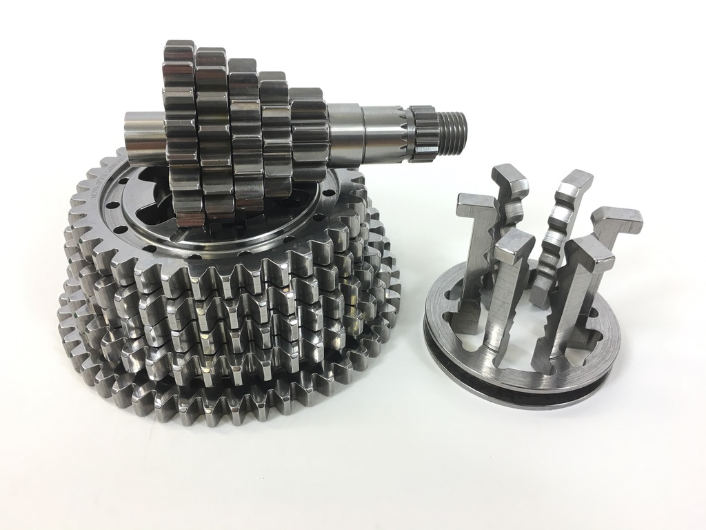
Complete MB5
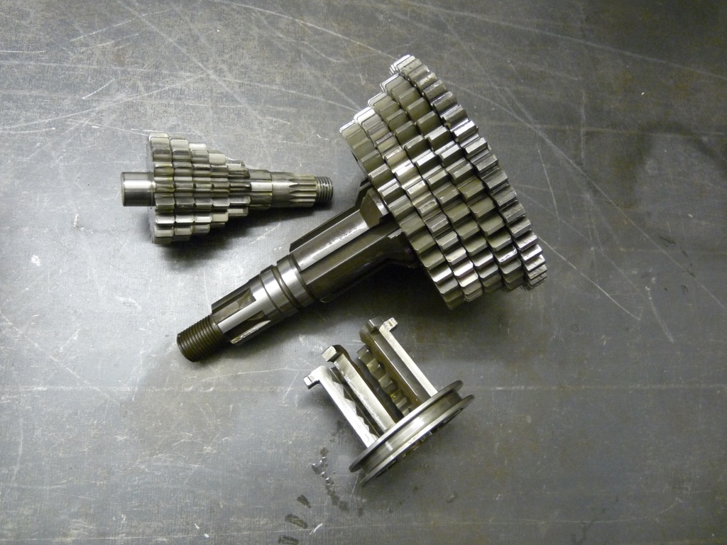
MB5 fitted to our Layshaft
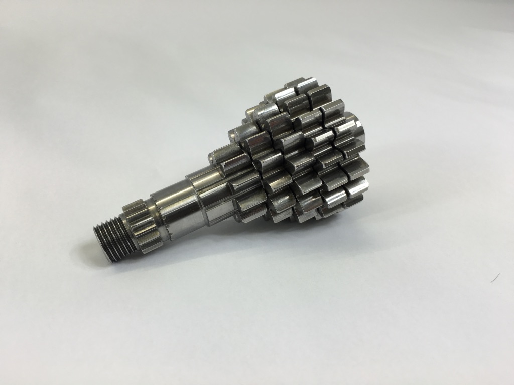
MB5 Cluster
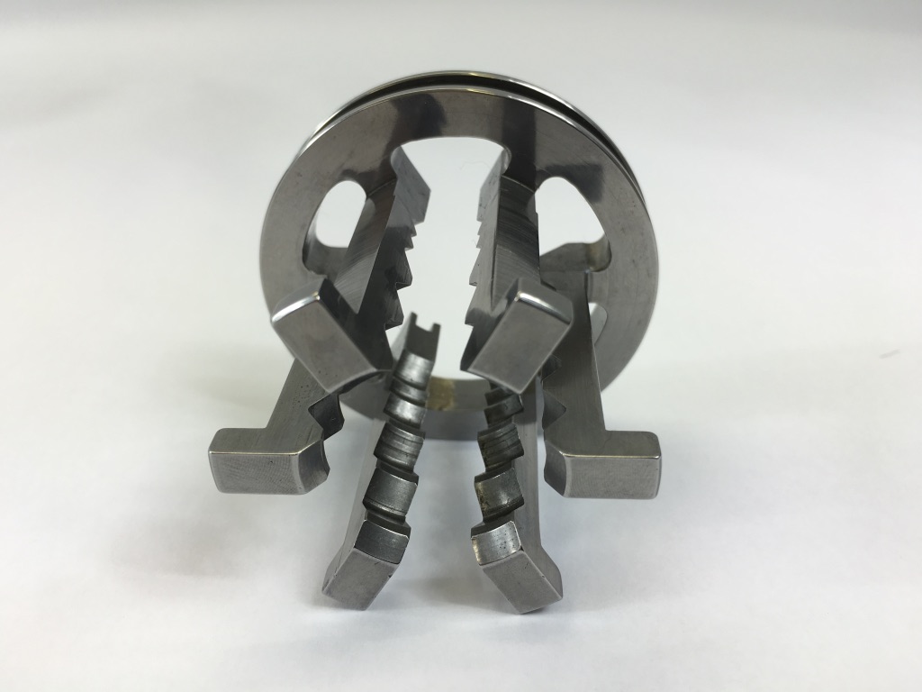
MB5 crusiform
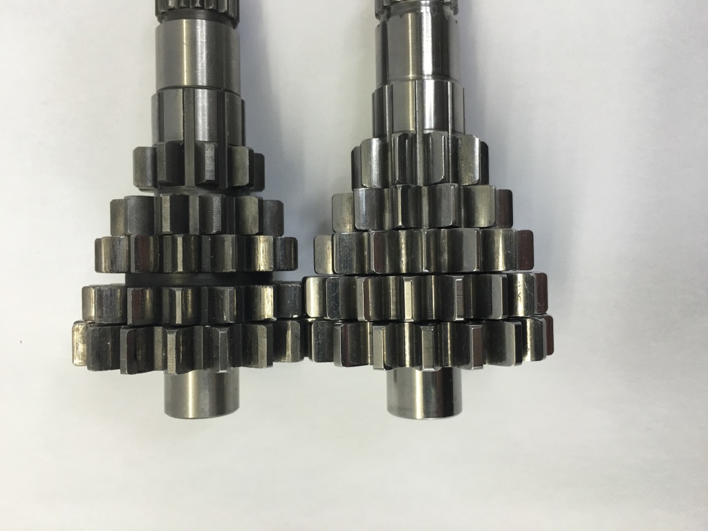
The difference with a 4 speed on the left MB5 on the right, shows we increased gear width in our design
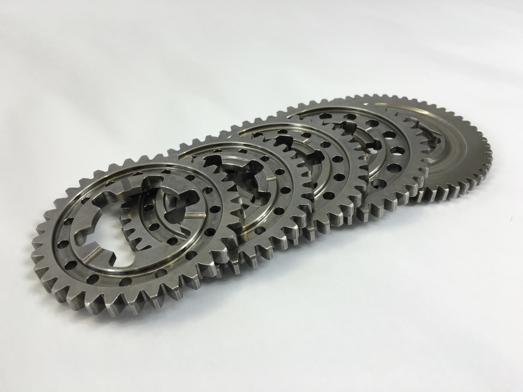
MB5 loose gears
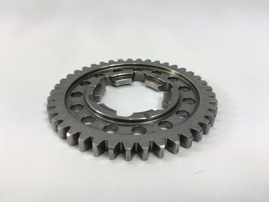
Lightened and polished
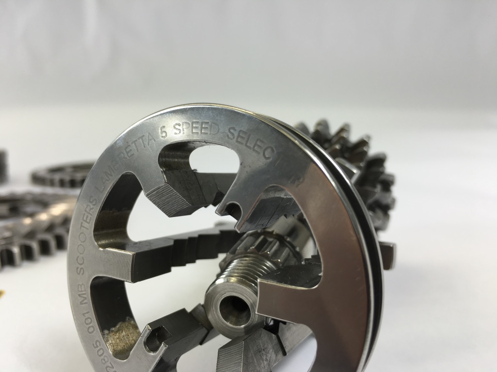
MB5 proud to put our name on it, but note the taper to push the selector balls in place
If you have any questions then email mark@mbscooters.co.uk


